Electrical Design
The TINAH Microcontroller
The “brains” behind the robot, the microcontroller board consists of two components:
1) Wiring, an open-source electronics I/O board and open-source programming environment based on the Atmel ATMega128 chip.
2) The TINAH board shield, a printed circuit-board shield designed and built for Phys253 and first used in 2009 by Engineering Physics students and staff. The shield acts as a “buffer” for protecting the digital and analog inputs and outputs of the Wiring board, and allowing for built-in functions.
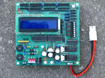
The TINAH Shield
|
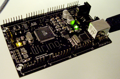
The Wiring Board
|
TINAH I/O Usage
The TINAH board consists of the following available input/output ports, along with the resources that were used in our implementation of the robot:
|
Available I/O:
Digital Inputs: 16 Analog Inputs: 8 PWM Outputs: 6 Servo Control: 3 |
Utilized I/O:
Digital Inputs: 5 Analog Inputs: 6 PWM Outputs: 3 Servo Control: 2 |
- Six analog inputs were used for QRD 1114 reflectance sensors, with five of them being used for the robot’s ability to track the black tape.Five digital inputs were used for mechanical switches, for use in collision detection.
- Two servo inputs were used for the robotic arm, to pick-up blocks. - Two motor inputs were used for driving the robot. - The last motor input was used to control the motor for the block lifting arm. |
Motor Control
Due to the TINAH board’s limited ability to provide current to attached devices, three motor-driver circuits were built to allow the TINAH to control the motor speeds and directions using Pulse-Width Modulation (PWM), while having the current provided by the battery source. These circuits, known as H-Bridges are comprised of high-current elements that allowed the motors to be driven at much higher powers than would be possible by using PWM outputs from the TINAH alone. By using 25A MOSFETs, the circuit shown below proved to be robust enough for the reliable operation of the robot.
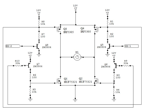
Schematic of the three H-bridge circuits used to drive the motors of the robot
The QRD 1114 Reflectance Sensor
This sensor acts as a robotic “eye” that produces infrared (IR) light, and varies its conductivity depending on the amount of infrared light that is reflected back to the phototransistor. Due to this, it is optimal in detecting the difference in the amount of reflected light between an object that is dark (black tape) and light (white wood). Unfortunately, this sensor is also very susceptible to interference from everything from natural light, 60 Hz (utility frequency) artificial sources and IR rangefinders on cameras. Due to this, the team created a housing to shield the sensors from these sources, to ensure the reliability of the tape-tracking algorithm.
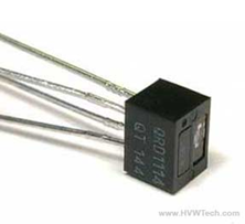
A picture of the QRD sensor used on the robot
|
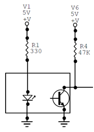
The QRD 1114 circuit with an output on the TINAH board
|
The Batteries
The batteries used were Nickel Metal Hydride (NiMH) cells at 16V. Although Lithium Polymer (LiPo) batteries were provided, the team found that the low internal resistance of the LiPo batteries, and the uneven switching time of the MOSFETs in the H-bridge circuits caused major current spikes, destroying several 10A fuses during the operation of the robot.
Tape Tracking
The tape-tracking inputs consisted of five QRD sensors to detect the black tape along the playing surface. Two main QRD sensors, placed at a distance from each other equalling the width of the tape on the bottom of the chassis act to steer the robot along straight portions of the tape. In addition, two more sensors at a larger width and mounted in front of the initial tape-tracking sensors act as feed-forward sensors for determining turn direction. The last sensor, mounted on the side of the chassis, acts to align the robot with certain tape lines to ensure accurate placement and stacking of the blocks.
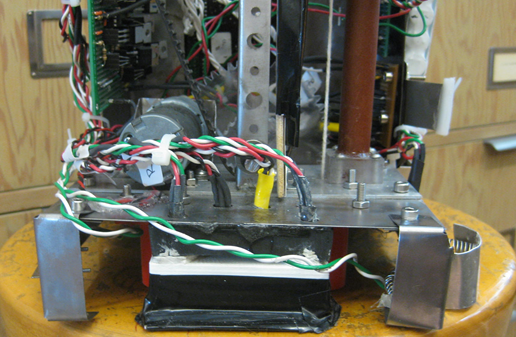
Front profile of the robot
The Arm Encoder
To detect the levels which the belt-driven arm would move to, the team used a single shielded QRD sensor attached to the arm, along with a stationary strip with several black lines – to act as an encoder for the system. This situation eliminated the four mechanical micro-switches, and used a similar implementation to the tape-tracking inputs as detailed above.
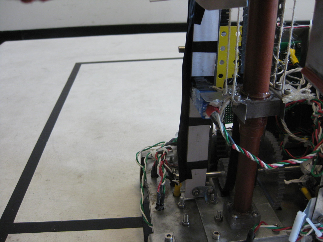
A view of the QRD sensor housing along the arm encoder
