Mechanical Design
Fabratory
The majority of sheet metal, and poly-carbonate, used for the chassis, gripper, and arm was prepared with the OMAX water jet cutter. This allowed for quick fabrication, with precise cuts that would be very difficult to make if using other methods. The schematics used by the waterjet were made in SolidWorks 2010, a 3D modelling program. We also used SolidWorks to design pieces to be made with a 3D printer. These pieces included housings for QRD reflection sensors, and ball casters. Other components were cut by hand with tin snips, drills, hacksaw and Whitney punch.
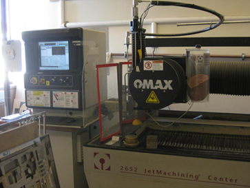
The OMAX water jet cutter
|
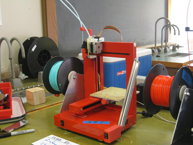
A 3D printer used on the project
|
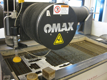
The OMAX platform
The Chassis
The chassis was designed with simplicity in mind. It consisted of 3 sheet steel components: motor mounts that ran the length of the robot on the underside to provide rigidity, a base surface upon which all topside components were mounted, and a back plate that the circuits and processor were mounted on. Driving power and steering control were provided by the rear wheels, which were directly mounted to 12V geared Barber Colman motors. The front wheels were ball casters, made using the 3D printer and a pair of 1/2" steel balls, press fit into the housing.
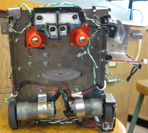
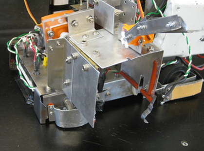
Bottom profile of the robot
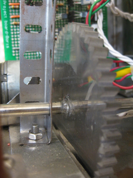
The gear driving the lifting belt
The Arm & Lifting System
The arm, gripper and lifting system required the most innovation of any system on the robot. We started by designing and fabricating the lift. It emulates a forklift system, using phenolic tubes in a telescoping setup that allows for extension. The arm is mounted to a poly-carbonate piece that is fitted to the outermost phenolic tube. This arm mount is attached to the chassis base by a string that runs over a shaft mounted at the top of the lift and acts as a 2:1 pulley, allowing the arm a 12" vertical range of motion. The lift is driven by a toothed belt system and 12 V geared Barber Colman motor with a 6:1 gear ratio. The gear ratio was selected by determining the maximal power output from the torque-curve using the data sheet of the Barber Colman.
The arm and gripper were made with sheet aluminium. The gripper design consists of two plates, connected by a door hinge: one bent to be L-shaped and fastened to the arm and one a square plate. The square plate was connected to a servo motor arm that provided the torque to close on and hold a block. The main challenge in designing the gripper was aligning the axis of rotation of the servo with that of the door hinge. On the top of the L-plate, another smaller servo motor was mounted with an arm that swings down at an angle to bring blocks closer in to the gripper.
The arm and gripper were made with sheet aluminium. The gripper design consists of two plates, connected by a door hinge: one bent to be L-shaped and fastened to the arm and one a square plate. The square plate was connected to a servo motor arm that provided the torque to close on and hold a block. The main challenge in designing the gripper was aligning the axis of rotation of the servo with that of the door hinge. On the top of the L-plate, another smaller servo motor was mounted with an arm that swings down at an angle to bring blocks closer in to the gripper.
The gripper arm
|
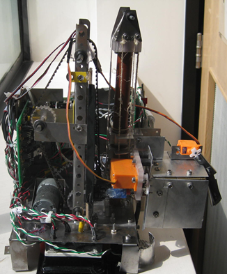
The lifting system
|
Manoeuvrability & Attitude
To align the robot parallel to the block depot, we mounted four micro-switches to the chassis, all low enough to be triggered by the 1/2 " wall surrounding the block depot. To guarantee the switches' being triggered, sheet metal bumpers were made to cover the switches. Two switches were mounted facing forward at both front corners, for initial detection of the block depot. One switch was on the left side of the robot, on a piece that covered the wheel; the bumper for this switch was designed such that it could be triggered from the side of the robot as well as the back. The last switch is on the left side, very near the front.
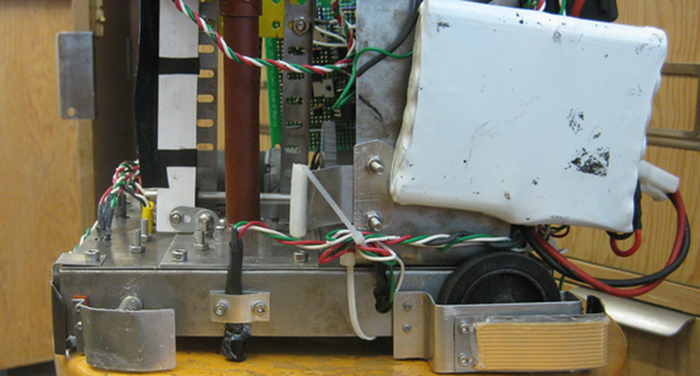
The QRD sensor and side switches
